With the screen chosen and working, the next step for creating the PiGRRL Switch was prototyping the controllers. Initially, I wanted something cheap and easy like a breakout board that acted as a Bluetooth HID joystick. I was immediately drawn to Adafruit’s EZ-Key which acts as a Bluetooth keyboard. At the time I’m writing this, however, it’s out of stock and seems to have been for a while. Additionally, because it acts as a Bluetooth keyboard and not a joystick, it rules out any possibility of adding analog controls in the future.
Another alternative to a Bluetooth HID breakout would be taking apart a cheap Bluetooth joystick and putting it in a 3D printed casing. However, I decided this would greatly reduce the design flexibility of the controllers and might make it difficult to reconfigure the controllers on the fly (i.e. using two JoyCons as one controller vs. using them as two separate controllers).
So with those two options off the table I decided instead to use a Bluetooth serial bridge. The HM-10 BLE and HC-05 Bluetooth 2.0 modules are both cheap and plentiful and provide a good solution at the cost of some extra work. These modules can be hooked up to the UART of an Arduino and paired via Bluetooth. Once connected, it acts as a virtual serial port in Linux, allowing the serial data to be read just as if the Arduino was connected via USB or FTDI. The only exception to this is that it doesn’t support firmware loading wirelessly.

The next step was setting up the initial design on a breadboard. Above is an Arduino Pro Mini, four pushbuttons wired to the digital pins, and the HM-10 BLE module. I decided to use the HM-10 because of the lower power requirements (BLE being an initialism for Bluetooth Low Energy). The code for the Arduino reads the values from the digital pins and prints out eight characters to signify which buttons are pressed (‘1’ for unpressed and ‘0’ for pressed). Right now I’m using a byte for each button which is wasteful, so I’ll go back at some point in the future and make the code more efficient so each button is represented by a bit.

Once everything was wired up and running I had a lot of trouble finding an app that could connect to the HM-10 as a serial terminal. Apparently the BLE standard has a lot of bells and whistles that make configuration a bit more difficult. After trying several different apps I eventually found Serial Bluetooth Terminal which can connect to both BLE and regular Bluetooth devices via a serial terminal. Above is screenshot of my phone connected to the controller with the button status being transmitted.
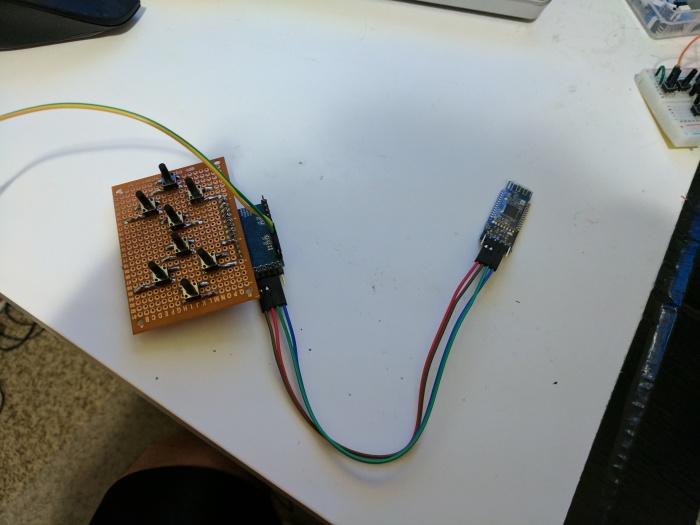

With my proof of concept working, I soldered everything onto a proto-board, this time with eight buttons to serve as a D-pad and four action buttons.
With that complete the next step was connecting to the Raspberry Pi over a serial terminal. Unfortunately, this was much more difficult than I expected. I could pair and connect to the HM-10, but couldn’t find a way to mount it as a serial terminal.
Rather than continue further down the rabbit hole, I decided to drop the BLE module for now and switch to the HC-05 modules I bought as a backup. Those have been around for years and have been used extensively with Arduino and Raspberry Pi. Once that module was paired and connected, mounting it as a serial terminal was as simple as using the following commands to connect and then print out the values read from the module:
sudo rfcomm bind /dev/rfcomm0 <MAC Address>
sudo cat /dev/rfcomm0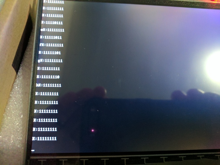

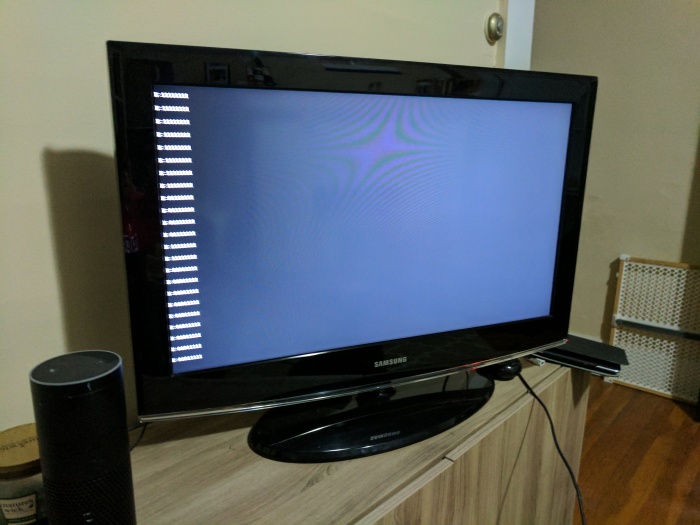
Lastly I connected the controller, screen, and Raspberry Pi to battery packs and verified everything still worked as suspected. Success! The next step is writing a program for Linux that reads the button data coming off the serial port and uses it to emulate a controller for the console.

[…] a follow-up to my last post, I wanted to go over the Arduino firmware I used for my primary controller test. Essentially what […]
LikeLike